
In the world of injection molding, every detail matters, and few are more critical than the gate. This small feature determines how plastic flows into the mold, affects the final part’s appearance, and even influences cycle times and cost. At Sussex IM, gate selection and placement are key considerations in every Design for Manufacturing (DFM) conversation we have.
This guide takes an in-depth look at common and specialized gate types, the role of gate design in part performance, and how strategic decisions made early in the process can drive better results.
What Is a Gate?
A gate is the passage point between the runner system and the mold cavity, where molten plastic makes its transition into becoming a part. Gate size, shape, and location all influence how material flows, cools, and ultimately forms the final product.
Even though gates are relatively small, their role is massive: they can make or break a part’s quality, performance, manufacturability and cost.
Gate Removal: What Happens After Molding?
As the molded part cools, a small amount of plastic solidifies at the gate. This leftover material, called a vestige or tab, must be removed, a process known as de-gating.
Depending on the gate style and tool design, de-gating can be:
- Automatic: Handled by the mold during part ejection
- Manual: Completed by an operator after molding
Gate style plays a major role in determining which method is used. A clean, automated separation may add tooling costs but saves time in high-volume runs, while manual de-gating might be acceptable for lower volumes, less complex parts or large part molding.
Common Gate Types in Injection Molding
Gate types are generally classified into two categories: manual trim and automatic trim. Each has ideal use cases depending on the part geometry, appearance requirements, and production volume.
Manual Trim Gates
These gates typically require human intervention to remove the vestige.
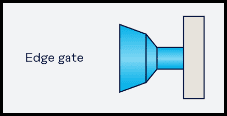
- Edge Gate: Positioned along the parting line, this gate is easy to machine and works well for square or rectangular parts with thicker walls. It is commonly used in multicavity tools or large part molding.
- Tab Gate: A variation of the edge gate, the tab gate includes a tab to help reduce stress and improve cosmetic outcomes. It’s often used on flat, thin parts where a clean break is needed.
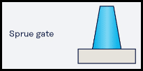
- Sprue Gate: Found in single-cavity molds, this gate connects the sprue directly to the part. It is simple to design but leaves a larger vestige and limits part placement flexibility. This method is commonly used for large part molding.
Automatic Trim Gates
These gates are designed to shear off automatically as the part ejects, reducing labor and improving cycle time.
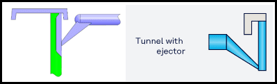
- Sub Gate (Tunnel or Submarine Gate): Located beneath the parting line, this gate is ideal when you want to hide the vestige on a non-visible surface. It is great for cosmetic applications.
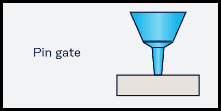
- Pin Gate: This gate uses a shearing action during ejection to break the gate from the part. Commonly used in 3-plate runner. It’s similar in result to a hot tip but designed for cold runners.
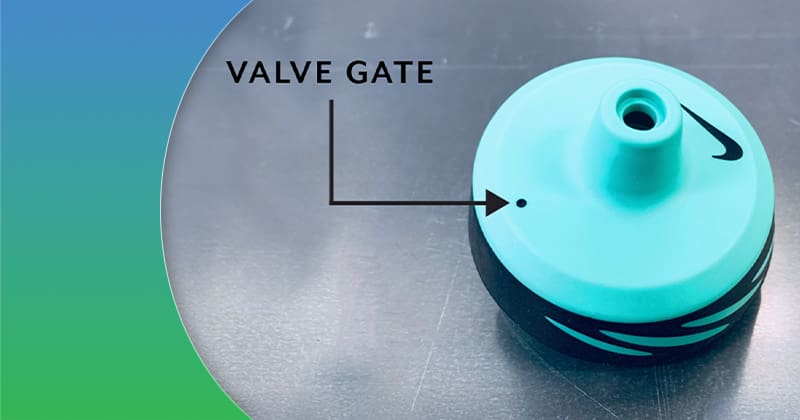
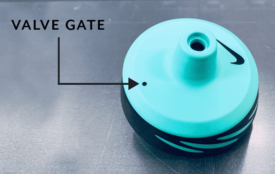
- Valve Gate: A valve inside the hot runner controls plastic flow, creating a near-invisible vestige. This gate is often used for parts with tight cosmetic requirements, high-precision needs, high cavitation and reduces runner waste.
- Hot Tip Gate: This gate requires a hot runner and delivers material into the top of the cavity. It works well for round or conical parts, high cavitation and reduces runner waste.
- Hot Edge Gate: The hot edge gate combines features of a hot tip and sub gate, entering from the side with clean separation. It supports high-cavitation molds and optimized flow.
Additional Gate Types
For complex geometries or specific performance needs, other gate types may come into play, including:
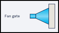
- Fan Gate: A wide, tapered gate that spreads flow evenly across a larger surface. It helps reduce flow marks on wide, thin parts but leaves a larger vestige.
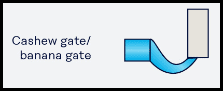
- Cashew (Banana) Gate: This gate is curved to allow gating in tight spaces, often exiting the part at a steep angle. It is common in applications where top or side gating isn’t possible.
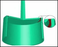
- Diaphragm Gate: This gate is used for cylindrical or tubular parts to ensure concentric flow and even packing. It’s often used in parts requiring tight tolerances around a center hub.
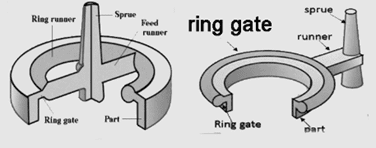
- Ring Gate: Encircling a central feature like a boss or core, this gate promotes uniform flow and packing for round parts.
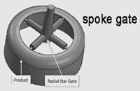
- Spoke Gate (3- or 4-Point Sub Gates): This gate directs flow into a part from multiple points, helping maintain balance and reduce warpage in round or hub-based parts.
- Pinpoint Gate (Three-Plate Mold Design): A very small gate used in high-cavitation tools, this gate allows for compact gate vestiges and clean parting, though it’s more susceptible to clogging if not properly designed.
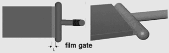
- Film Gate: A thin, wide gate that allows plastic to flow across a broad section of the part; ideal for flat parts but typically requires trimming.
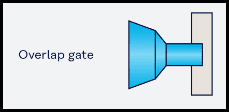
- Overlap Gate: This gate is rare in thermoplastics, but used occasionally for specialized flow control needs or unusual geometries.
How Gate Type and Placement Impact Part Quality
Gate Type
The type of gate used in an injection mold plays a significant role in the visual and functional outcome of the final part. Certain gate styles leave larger or more noticeable vestiges, which can impact part aesthetics, especially when the gate is placed on a visible surface. Cycle time is another factor – gates designed for hot runner or automatic trim systems can often speed up production by minimizing the need for secondary operations. Scrap rate is also affected by gate design; some gate types help reduce runner waste, making the process more efficient and environmentally responsible. Mold cost ties into all of this, as simpler gate types are typically less expensive to implement but may require additional trimming or finishing steps after molding.
Gate Location
Where the gate is placed on the part has a direct impact on how the mold fills and how the part performs. Proper gate placement ensures that the mold cavity fills completely and evenly, which is critical for maintaining part integrity. Gates should typically be positioned at the thickest area of the part to minimize defects like warpage and sink. The direction of flow introduced by gate location also affects shrinkage patterns, which in turn influence dimensional stability. From a cosmetic standpoint, gates should be positioned on non-visible surfaces whenever possible to reduce the appearance of vestiges or flow marks on finished parts.
Key Factors When Choosing a Gate
Sussex IM analyzes all aspects of your part and process to recommend the most efficient gating strategy. Factors we consider include:
- Part geometry and wall thickness
- Cosmetic requirements
- Flow distance and fill time
- Material type and viscosity
- Production volume and mold cavitation
- Ease of trimming and automation opportunities
We balance these needs against cost, lead time, and tool complexity to provide a solution that performs over the long run.
Troubleshooting Common Gate Issues
Gate-related problems can affect both the appearance and performance of molded parts. Some common issues include:
- Gate Blush: This appears as hazy or discolored marks near the gate and is typically caused by overheating. It can often be resolved by lowering the melt temperature or switching to a gate style that provides better thermal control.
- Gate Vestige: This is excess material left on the part after molding, which can be minimized through improved trimming techniques or by modifying the gate design for a cleaner break.
- Gate Drool: This occurs when plastic oozes from the gate or nozzle and can be prevented by using shutoff valves or optimizing temperature settings to maintain control over the material flow.
Regular mold maintenance, optimized cooling, and precise gate sizing all contribute to minimizing these common issues and improving long-term mold performance.
Best Practices for Gate Design and Maintenance
Designing an effective gate system starts with choosing the correct size and shape for the part and material being molded. Gates should be appropriately sized to ensure smooth flow and avoid excessive shear. Incorporating venting near the gate is also critical – this allows trapped gases to escape, which helps prevent burn marks and incomplete fills. For structural integrity and optimal aesthetics, gates should align with thicker walls to reduce the risk of sink marks. Whenever feasible, designs should allow for easy de-gating, reducing the need for manual trimming or secondary processes. Ongoing mold maintenance is equally important: regular inspection and cleaning of gate areas help prevent material buildup, wear, or blockage that could affect long-term performance.
The Sussex IM Difference
At Sussex IM, gate selection is never one-size-fits-all. With more than 60 injection molding machines and an expert team of engineers, toolmakers, and project managers, we analyze each project with a focus on functionality and performance, speed to market, cost efficiency, and visual and dimensional quality.
Whether you’re working on a simple single-cavity mold or a complex, high-cavitation tool, we have the experience and in-house capabilities to support you from design to delivery. Contact us today!